4.1.2 FEMM 2D FEA Results
For initial concept analysis the readily available two-dimensional finite element program FEMM is used. FEMM includes a simple geometric modeler, a triangular mesh generator, standard and user-defined material libraries, magneto-static and time-harmonic analysis engines, and a graphical post-processor.
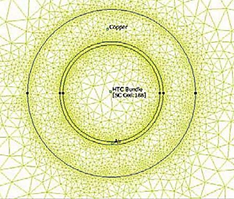
The geometry of the MACE system lends itself to an axisymmetric model that allows one to include the three-dimensional aspect of the system in a simple way. For the purpose of this analysis, the MACE coil set has a diameter of 60 cm, the superconducting storage coil has a diameter of 3 cm, the coaxial load coil has an inner diameter that is spaced 0.1 cm from the outer diameter of the superconducting storage coil and has a thickness of 1 cm. The finite element mesh generated by FEMM is shown in Figure 5. The overall mesh contains 8626 nodes. The mesh density in the load coil conductor should be sufficient to adequately represent the skin depth behavior at 1000 Hz for analysis of coil coupling under time-harmonic excitation conditions.
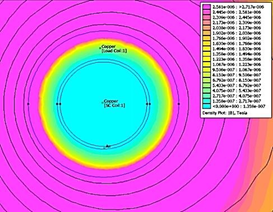
Figure 6 shows the results of a magneto-static analysis for the initial charged coil state, with the expected magnetic flux density levels around the coil with 150,000 A-turns in the superconducting coil. The maximum magnetic flux density in the neighborhood of the superconducting coil is limited to approximately 2 T for the proof-of-concept experimental system; full-scale MACE systems are expected to utilize magnetic flux densities near 6 T or greater in order to maximize energy storage density.
Figure 5. Finite element mesh generated by the FEMM software of the 2-D MACE model
|
Figure 6. Expected magnetic flux density levels around the coil with 150,000 A-turns in the superconducting coil |
In order to examine the coupling between the load coil and the storage coil, the load coil is supplied with an excitation current of 1 A at a frequency of 1000 Hz; this ensures that the skin depth of the copper in the load coil is << thickness of load coil conductor, which will in turn ensure that the magnetic flux density within the load coil region, where the superconducting coil is, remains close to zero. A 1-A current magnitude and assuming 1 turn for both the load and superconducting coils allows us to quickly calculate and compare inductances and mutual coupling.
Figure 7 shows the magnetic flux density plot for the time-harmonic analysis at 1000 Hz. With excitation current applied to the load coil, the magnetic flux density at the storage coil location is essentially zero due to the skin-depth behavior of the load coil conductor. Nevertheless, there is magnetic coupling between the two coils.
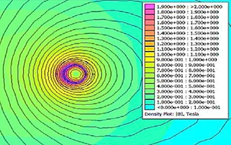
Figure 7. Magnetic flux density plot for the time-harmonic analysis of the MACE coil at 1000 Hz
The finite element analysis was used to extract circuit parameters for a SPICE simulation of the transient behavior MACE system, providing values for self, mutual, and leakage inductances. Figure 8 shows the circuit parameters extracted using the FEMM analysis at 1000 Hz. Note that windings 2 and 3 are the two (2) halves of the load coil.
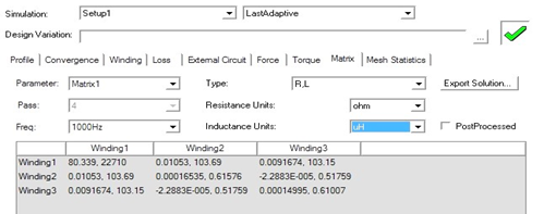
Figure 8. Circuit parameters of MACE system extracted using FEMM analysis at 1000 Hz
The non-zero off-diagonal terms of the coupling matrix in Figure 9 (below) show this coupling explicitly.
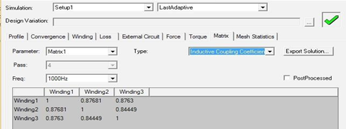
Figure 9. The non-zero off-diagonal terms of the coupling matrix demonstrate coupling between primary and secondary coils